
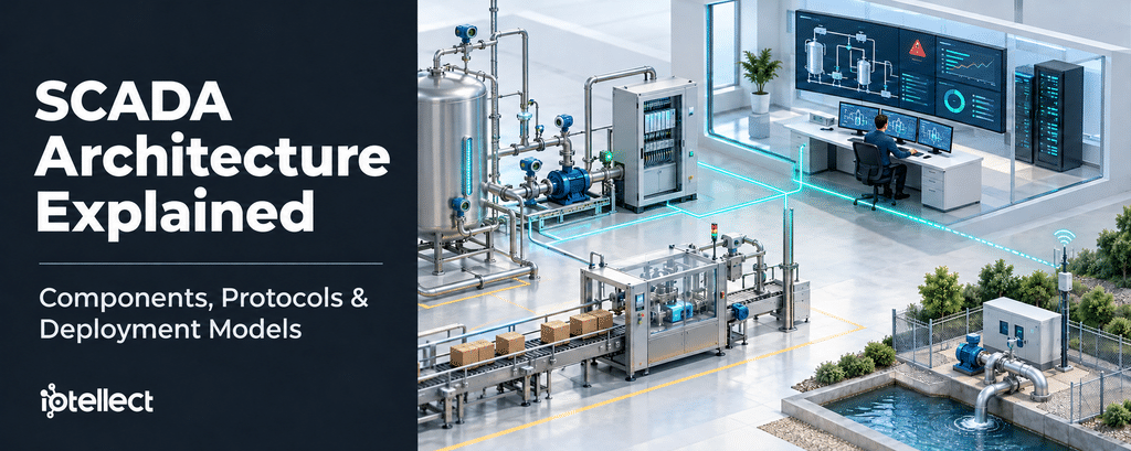
Identical SCADA diagrams can hide different behavior when a remote link drops. The difference lies in where each function runs, rather than in the label on the drawing. This guide explains SCADA architecture role by role: components, data and command paths, protocols, deployment configurations, failure and security behavior, and connections to MES and ERP. It draws on public standards, government guidance, and an illustrative plant example.
What Is SCADA Architecture?
SCADA architecture is the arrangement of field devices, controllers, communications, and supervisory software that together collect data from dispersed sites, send it to a control center, and let operators monitor and control the process. Sensors, actuators, PLCs, and RTUs work at the field sites. A supervisory server, HMI, historian, and alarm functions typically sit at the center.
NIST SP 800-82 Rev. 3 describes a typical SCADA system as a control server at a control center, communications equipment, and field sites where RTUs or PLCs control the local process.
NIST does not prescribe a single diagram. It identifies the Purdue model, ISA-95 levels, a three-tier IIoT architecture, or a combination of these models as possible ways to organize OT network segmentation. The Purdue model is a reference model rather than a standard. This guide therefore treats levels as logical roles.
ISA’s dedicated SCADA standard, ANSI/ISA-112.00.01-2025, includes a functional architecture model and lifecycle framework applicable to SCADA projects. It provides another reference for organizing SCADA functions without making one implementation diagram suitable for every project.
SCADA System Components and Their Responsibilities
Each component below has a main responsibility. Real implementations may combine several functions, so the table lists roles rather than separate boxes that every system must contain.
| Component | Responsibility |
|---|---|
| Sensor | Measures a physical property and sends it to the controller. |
| Actuator | Acts on the process in response to the controller’s command. |
| PLC | Runs programmed logic and closes local control loops. In SCADA, it may also perform functions associated with an RTU. |
| RTU | A remote terminal unit collects field data and passes commands between field devices and the central server. Local control capabilities depend on the device. |
| IED | A processor-based field device, such as a protective relay or meter, that monitors or controls equipment and may act on local programming. |
| Communication infrastructure | Moves data and commands between the control center and field sites over serial or network links and telemetry media. |
| SCADA / control server — MTU or master | Hosts supervisory software, collects and processes field data, and sends setpoints and commands. Storage may be integrated or handled by a separate historian. |
| HMI | Shows process status and history and lets authorized operators adjust setpoints and parameters. |
| Historian | Collects and stores process data and related records for analysis. Storage may be organized hierarchically, from site to plant. |
| Alarm system | Notifies operators of abnormal conditions, supports their response, and maintains alarm and event records. |
| Engineering workstation | Configures and programs controllers and system applications. |
| Safety instrumented system, where present | Brings or maintains the process in a safe state, often independently of the basic control system. |
In a typical control-center arrangement, HMIs, engineering workstations, and the historian communicate over a local area network. The control center may also generate supervisory actions in response to detected events.
The alarm-management standards ANSI/ISA-18.2 and IEC 62682 address the process industries rather than SCADA as a category. Where a safety instrumented system exists, it is often independent of the basic control system. The specific arrangement depends on the process and its safety requirements.
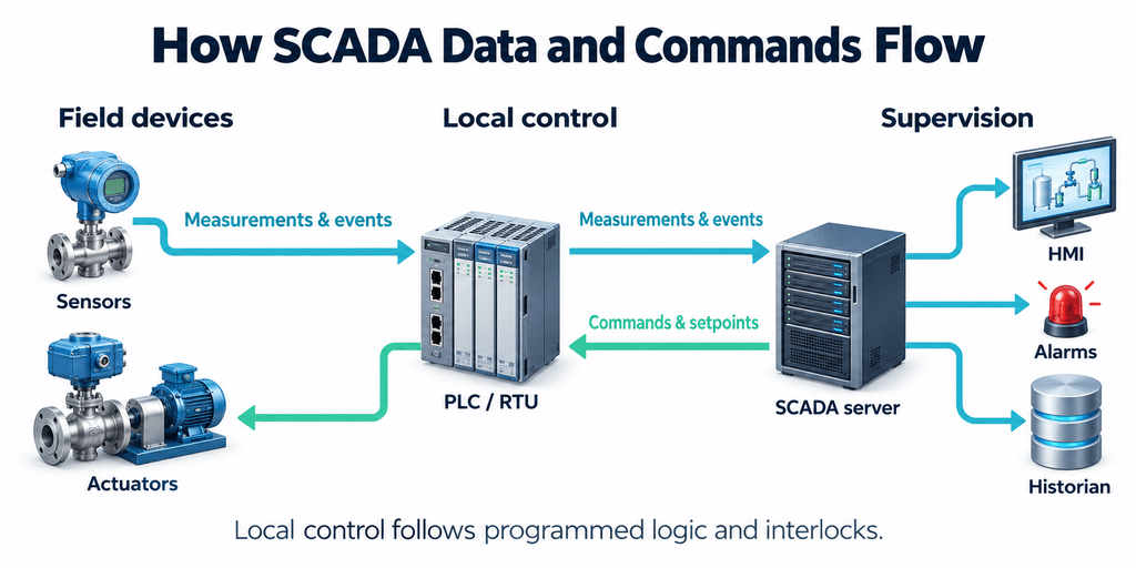
How Data and Commands Move Through a SCADA System
Consider a food and beverage plant: an illustrative composite rather than a customer case. PLCs run the filling and packaging lines, and a wastewater lift station on the far side of the site runs on an RTU linked to the control room over radio or cellular. The same SCADA layer supervises the lines and the remote station.
Measurement Path: The Production Lines
The PLC reads measurements and uses them to execute its local control logic. The SCADA server collects line data through polling, for instance over Modbus, or through an OPC UA subscription.
Modbus uses a request/reply model. With an OPC UA subscription, the server samples the monitored values at a negotiated interval, subject to the implementation’s capabilities. How the OPC UA server obtains values from its underlying source is implementation-specific.
An OPC UA DataValue includes a quality status, such as Good, Uncertain, or Bad, and can include a source timestamp. That timestamp should be generated as close as possible to the source of the value. A consistent time reference across OT devices helps align records from different systems.
Measurement Path: The Lift Station
The RTU controls the pumps locally. The server can poll it or use DNP3 event reporting and unsolicited responses where supported. In DNP3 terminology, the RTU acts as an outstation, and unsolicited reporting is not available on every outstation.
A third option is MQTT under the Sparkplug specification. An edge node publishes its current metrics in a BIRTH message and can then report changes by exception.
Report-by-exception is useful when repeated polling would consume limited bandwidth or incur unnecessary communication costs. The benefit depends on the number of changing values, reporting requirements, and link characteristics.
Command Path
An operator changes a setpoint on the HMI, the server sends it, and the controller acts according to its programmed logic and sensor feedback.
Safety functions that must survive a lost supervisory link need appropriate local control logic or independent safeguards. The command path should also provide enough feedback for operators to distinguish a command being issued from the equipment reaching the requested state.
SCADA Communication Protocols: Where Each Fits
The table below places protocols according to their intended scope. The “where it sits” column describes a typical architectural fit rather than a mandated layer.
For many industrial protocols, security depends on optional features, a separate secure variant, or additional network controls. It should not be assumed from the protocol name alone.
Modbus is a request/reply protocol. Modbus TCP normally uses port 502. The Modbus Organization introduced a separate Modbus Security protocol that uses TLS with traditional Modbus communication on port 802.
OPC UA supports both client/server and publish/subscribe models. Its scope extends from device-level communication to enterprise and cloud integration.
| Protocol | Where it sits | Typical use | Communication model | Security considerations |
|---|---|---|---|---|
| Modbus RTU / Modbus TCP | RTU: serial links, commonly RS-485 or RS-232. TCP: Ethernet, normally port 502. | Messaging between controllers, meters, and other devices. | Request/reply, commonly through polling. Register meanings are device-specific. | Traditional Modbus does not provide built-in authentication or encryption. The separate Modbus Security protocol adds TLS-based protection. Check device support and configuration. |
| OPC UA | From device level to enterprise and cloud integration. | Industrial information exchange with structured data and metadata. | Client/server and publish/subscribe. Subscription timing depends on negotiated settings and server capabilities. | Supports security modes including None, Sign, and SignAndEncrypt. Verify enabled policies, certificate handling, and access controls. |
| OPC Classic — DA, legacy | Windows COM/DCOM interfaces between servers, HMIs, and supervisory clients. | Process values with timestamps and quality information. | Read, write, and subscription-based update notifications. | Relies on legacy COM/DCOM security and configuration. |
| DNP3 — IEEE 1815 | WAN telemetry between master stations and outstations, including RTUs and IEDs. | Electric transmission and distribution, water, and wastewater. | Poll-response, report-by-exception, and unsolicited responses where supported. Events may include timestamps. | Secure Authentication provides authentication rather than encryption. Verify the implemented version and any additional transport protection. |
| IEC 60870-5-101 / -104 | 101: serial telecontrol links. 104: TCP/IP networks. | Telecontrol of geographically distributed processes. | Telecontrol services supporting measurements, events, and commands. | Security provisions depend on applicable extensions and the implemented system. Base protocol support alone does not establish a secure connection. |
| IEC 61850 | Substation and power-utility automation, between IEDs and station-level systems. | Power utility automation. | Client/server services, including MMS, and publisher/subscriber services. | Relevant protections are addressed by the IEC 62351 family. Confirm support for the required services and security mechanisms. |
| MQTT 3.1.1 / 5.0 | A broker between edge nodes or gateways and consumers. | Machine-to-machine messaging, including bandwidth-constrained applications. Payload-agnostic. | Broker-based publish/subscribe. | Configure authentication, authorization, and secure transport. MQTT alone does not define an industrial data model. |
| Sparkplug 3.0 | Conventions on top of MQTT, between edge nodes and host applications. | Industrial data exchange, including SCADA and HMI applications. | Supports report-by-exception and BIRTH/DEATH messages for state awareness. | Does not replace broker access controls or transport security. |
| PROFINET / EtherNet/IP — controller-level context | Controllers and I/O devices. | Cyclic I/O exchange and other industrial control services. | PROFINET uses provider/consumer I/O exchange. EtherNet/IP supports producer/consumer I/O and explicit request/reply messaging. | Security capabilities depend on the specification, device support, and configuration. Keep control-network exposure restricted. |
The NCSC-led guidance on secure OT connectivity recommends restricting industrial control protocols to appropriate OT network segments and brokering OT-to-IT exchange through controlled interfaces, such as services in a DMZ.
For the lift station’s cellular connection, protocol selection should consider latency, intermittent connectivity, event delivery, bandwidth, and equipment support. A protocol’s ability to report by exception does not establish how much bandwidth a particular installation will save.
A security feature in a specification does not prove that it is enabled on a deployed connection.
Standalone, Client-Server, Distributed, and Edge Deployments
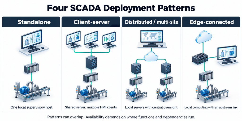
The labels commonly used for SCADA deployments describe different things: how many supervisory hosts exist, how roles are split, how widely sites are distributed, and whether there is an uplink beyond the plant. They are not stages of maturity.
The table assumes that field instruments, controllers, and power remain available, and that each site’s control logic and required inputs are local. Here, “standalone” means one local supervisory host with its operator interface and field connections.
| Configuration | Structure | Redundancy options | Loss of WAN to remote sites | Loss of central or supervisory server | Loss of internet or cloud link |
|---|---|---|---|---|---|
| Standalone | One local supervisory host with its operator interface and field connections. Specify whether HMI, alarms, and history share that host. | An added standby host, backups, and tested restoration procedures. | Remote telemetry and commands require a surviving path. Local controllers continue their configured logic or enter a configured safe state. | Services hosted only on that computer stop. Controllers continue their own logic. Supervision returns through recovery or a standby. | No effect on functions that have no internet dependency. |
| Client-server | Servers handle acquisition, alarms, and history. Several HMI clients connect over the plant LAN. | Standby servers, supported hot or warm failover, and redundant networks. Additional clients alone do not duplicate server services. | Remote-site visibility and commands require a surviving or alternate path. | Clients lose the failed server’s services unless a configured standby takes over. Controller autonomy is separate from HMI continuity. | A self-contained plant deployment retains local supervision. Services beyond the failed connection become unavailable. |
| Distributed / multi-site | Several servers or control centers each manage a subset of data or sites. Regional, primary, and backup centers may communicate over a WAN. | Backup centers, separately located standby systems, alternate communication paths, and redundant networks. Distribution alone does not replicate application or historical state. | Disconnected sites lose cross-site services. Local screens, alarms, and history survive only where hosted locally. Configured buffering has finite capacity. | Independent servers retain their functions. Functions hosted only at the failed center stop. | Private LAN or WAN functions can continue. Internet-routed cross-site and cloud services lose that route. |
| Edge-connected — a distributed variant | Local control and computing nodes connect to an enterprise or cloud tier. The placement of edge functions depends on project requirements. | Distributed-system options apply. An edge gateway still needs appropriate maintenance, monitoring, and protection. | Remote platforms and brokers may become unreachable. Local functions depend on their actual placement. | Local control and supervision can remain available where hosted independently. A gateway alone does not prove local supervision. | Upstream functions lose connectivity. Independent local functions continue. Buffered data is forwarded later only if configured and within retention limits. |
In distributed SCADA architecture, several servers or control centers each own a subset of data or sites. Large systems may use sub-control servers, with communication between primary, backup, and regional centers passing over WAN connections.
For the example lift station, the label matters less than the location of its pump logic, alarms, and history when the WAN fails.
The edge-connected variant adds a gateway or edge server that links local controllers to an enterprise or cloud tier. It can overlap with a distributed deployment rather than forming a completely separate architectural category.
The gateway is also another network boundary device to maintain and monitor. Its presence alone does not establish that local screens, alarm processing, or historical storage will survive a lost uplink.
What survives depends on which functions run locally and which supporting services they require. Iotellect lists local automation, alarms, and store-and-forward buffering among the offline capabilities of its industrial edge platform.
Redundancy, Security, and Communication Failures
SCADA systems often incorporate redundancy to improve availability. However, redundancy does not automatically protect against a malicious attack or a shared failure point.
Alternate communication paths need protection comparable to the primary path. The behavior of commands in flight, alarm acknowledgments, and historian writes during failover must be tested for each design.
Segmentation and Controlled Connectivity
Network segmentation and enabled protocol-security features both matter. Where a connection lacks authentication or encryption, segmentation and documented compensating controls help manage the exposure.
IEC 62443-3-2 describes dividing the system under consideration into zones and conduits. In practice, this means defining groups of assets with appropriate security requirements and controlling the communication between them.
Government OT guidance also emphasizes removing unnecessary public internet exposure and controlling external data exchange through intermediary services.
In the illustrative plant, the lift station has its own network segment and a secured connection to the control center. This limits the station’s exposure while allowing the required telemetry and commands.
Loss of Internet or Enterprise Services
An on-premises SCADA system can continue without internet access when its control, supervisory, and supporting services are independent of that connection.
Supporting services need explicit attention. Authentication, name resolution, time synchronization, and other dependencies can make a locally hosted system reliant on an upstream network.
Test these dependencies rather than assuming that an on-premises server guarantees autonomous operation.
Loss of the Central Server
If the central server fails, controllers can continue their local programs when their required inputs and services remain available. Central screens, alarm handling, and historian writes stop unless a configured standby takes over.
Local automatic control and fail-safe behavior must be designed and configured for the process. They should not be assumed from the presence of a PLC or RTU.
Loss of the Remote-Site Connection
If the lift station’s radio or cellular link fails, local control can continue where decisions are made on site.
The control room loses its live view of the station and its ability to issue remote commands. If that loss is unacceptable, the architecture may need an alternate communication path.
Station values should clearly show communication loss or stale data. Gap data can reach the historian later only if buffering is configured, storage limits are respected, and the records retain their historical timestamps.
Buffer depth, overwrite behavior, and backfill handling are implementation-specific.
A warning sign is that every site’s supervision, authentication, name resolution, or time service depends on one upstream gateway. An outage at that gateway can disrupt every dependent site.
Connecting SCADA to MES and ERP
ISA-95 levels describe functional boundaries rather than fixed product categories. SCADA implementations can span supervisory and operations functions, while MES typically manages manufacturing execution and ERP manages enterprise planning and business activity.
ISA’s overview of ISA-95 emphasizes the interface between manufacturing operations and enterprise systems. The framework helps define what information crosses that boundary without requiring each software product to occupy exactly one level.
These functions also operate on different timescales. Equipment control reacts to process conditions, manufacturing operations coordinate production across jobs and shifts, and enterprise systems plan and account for business activity.
A manufacturing execution system connects these activities by turning production requirements into executable work and reporting what was completed.
In the example plant, the MES releases a job order to a packaging line. The order may include:
- The material lot.
- The line to use.
- The required production quantity.
- A use-by date to print on labels.
- A reference to the applicable recipe or work procedure.
The automation system executes the relevant equipment functions, and a job response reports the work performed.
Enterprise traffic should pass through controlled integration services. Business systems should not require unrestricted direct communication with PLCs or field devices.
Iotellect’s article on how SCADA, MES, and ERP work together explains where each system’s responsibilities begin and end.
Common SCADA Architecture Mistakes
The following list covers architecture and the operating practices around it. The examples draw on government advisories, investigations, and OT security guidance. They illustrate possible failure patterns rather than establishing how frequently each occurs in manufacturing.
Exposing PLCs or HMIs to the Internet
Internet-exposed operational interfaces create opportunities for unauthorized changes to setpoints, equipment states, and alarm settings.
Use controlled remote-access arrangements, restrict permissions, and remove unnecessary exposure.
Using Default or Missing Passwords
Default or absent credentials can give an attacker a direct path into accessible equipment.
Replace defaults, use appropriate authentication, and restrict accounts to the functions each user needs.
Using One Network for Everything
Combining control and non-control traffic on a single network creates difficulties in protecting control traffic and meeting its operating requirements.
Separate communication according to function, risk, and performance needs.
Building OT That Cannot Run Without IT Services
When required DNS, authentication, or other services sit only in the enterprise network, the OT environment inherits that network’s availability.
Identify which services must remain available locally and test operation with the IT connection unavailable.
Creating Redundancy That Shares a Failure Point
Dual controllers or servers can still fail together when they depend on the same switch, network, power source, or shared service.
Review the complete dependency chain rather than counting duplicate devices.
Changing the Live System Without a Fallback Copy
Test changes in an appropriate offline or non-production environment. Keep recoverable copies of firmware, controller logic, application configurations, and essential data.
Restoration procedures should be tested before they are needed during an outage.
Having No Manual Fallback
Define how the process can be operated, placed in a restricted mode, or shut down safely when normal supervision is unavailable.
Where manual operation is appropriate, operators need documented procedures and practice.
Allowing Alarm Floods
Too many simultaneous alarms can prevent operators from identifying the conditions that require immediate action.
Assign priorities, document expected responses, and review nuisance or duplicate alarms. An alarm should support a decision rather than simply repeat every abnormal value.
Where Iotellect Fits
Iotellect is a software platform for building this kind of system. Its SCADA software integrates a historian, alarms, and reporting. Alarm functions use the same tag database as operator screens and historical data.
Configuration, data source setup, and runtime dashboards run in a browser. The server runs on Windows and Linux, including ARM-based hardware, with cloud, on-premises, edge, and hybrid deployment options.
Its distributed architecture supports multiple servers with centralized management. The platform lists industrial connectivity options including OPC UA, OPC DA/HDA/AE, and Modbus.
Visual configuration covers data bindings, screen logic, alarm rules, and report layouts, with scripting available for cases that require it. The MES product page also describes access to the same tag database used by SCADA.
For hybrid deployments, local availability depends on the functions and dependencies configured at each node. Engineers should verify local operation, buffering, and recovery behavior for the specific project.
Iotellect supplies the software, a demo, training, and integration support. The customer’s engineers or a system integrator design, build, and commission the project.
Frequently Asked Questions
What Are the Main Components of SCADA Architecture?
The main components are sensors, actuators, PLCs or RTUs, communication equipment, a supervisory server, an HMI, a historian, engineering tools, and alarm functions. Real systems combine these roles in different ways, and several functions may share the same hardware.
What Is the Difference Between a PLC, an RTU, and SCADA?
SCADA is the supervisory system that collects data from equipment and sites and lets operators monitor them and issue commands. A PLC runs programmed local control logic. An RTU typically collects remote telemetry and exchanges commands, with local control capabilities depending on the device. Their functions can overlap: some PLCs perform RTU roles, and some RTUs execute substantial local control logic.
How Does Distributed SCADA Architecture Work?
Several servers or control centers share the work, each managing a subset of equipment or sites. Regional and central systems exchange data over a network or WAN. Distribution alone does not replicate applications or historical records. What a site retains after a failure depends on whether its logic, screens, alarms, and history are hosted locally. Edge-connected designs add local computing and an enterprise or cloud uplink.
Can SCADA Continue Operating Without an Internet Connection?
Yes, if it is designed for it. A self-contained on-premises SCADA system can continue without internet access when its control, supervisory, and supporting services are independent of that access.
If the only connection to a remote site fails, the control room loses live telemetry and remote commands. Local controllers can continue their configured logic or enter a configured safe state when the required inputs and services remain available.
If the central server fails, functions hosted only there stop unless a standby takes over. Buffered data can be forwarded after reconnection within the implementation’s retention limits and with its original timestamps.
How Does SCADA Integrate with MES and ERP?
SCADA provides equipment status, measurements, alarms, and process events. MES manages production execution and links those records to jobs, materials, quality, and traceability. ERP handles planning, inventory, purchasing, and business accounting.
Production requirements and job instructions move toward operations, while confirmed production results move back toward business systems. Controlled integration services manage the exchange between these functions.