

The difference between SCADA and DCS in short
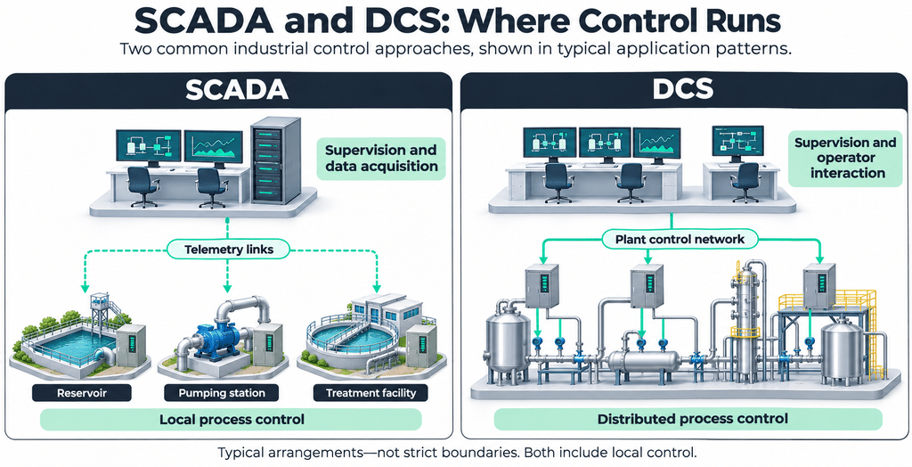
SCADA and DCS differ mainly in their typical emphasis. SCADA emphasizes supervisory control and data acquisition across connected, often geographically dispersed assets, while a DCS typically integrates distributed process control within a plant. Real implementations can overlap, and the two are often networked together, as NIST SP 800-82 Rev. 3 (2023) notes.
The table compares typical emphases. Product capabilities and project designs can overlap.
| Aspect | SCADA (typically) | DCS (typically) |
|---|---|---|
| Control responsibilities | A control server collects and processes site data, raises alarms and sends set points or commands. RTUs or PLCs at the field sites control the local process. Control can be automatic or by operator command, depending on the system’s sophistication and setup. | A supervisory level coordinates distributed controllers that run the plant’s feedback or feedforward loops around set points. The supervisor sends set points to the controllers. |
| Geographic scope | Typically dispersed assets – distribution networks, pipelines, grids – where centralized data acquisition is as important as control. | Typically production systems within one site (“the same geographic location”). The line can blur: NIST notes hybrid implementations. |
| Engineering tools | Engineering workstations at the control centre. Controller logic can be programmed with the controllers’ own tools, for example in IEC 61131-3 languages, and the SCADA application can be configured separately with its own database. Configuration data must remain consistent across tools. | Controllers are maintained through engineering workstations. How far configuration, logic, graphics and history share an engineering environment depends on the product. |
| Communications | Telemetry between the control centre and field sites over media such as leased lines, fiber, radio, cellular or satellite. SCADA was designed for communication challenges such as delays and data integrity. Links between locations typically use external or WAN connections. | A plant control network between the supervisory level and the controllers, plus fieldbus to field devices. Protocols such as Modbus and Fieldbus are often used on control networks. |
| Alarms | Centralized alarming at the control centre. The server watches for priority interrupts from field-site alarm systems (NIST example). | Alarms from the BPCS and from the SIS are presented to operators at consoles. Alarm management under IEC 62682 / ISA-18.2 covers process facilities whichever architecture is used. |
| Historian | A data historian at the control centre logs site data for trends and reports. Data from a site cut off by a link outage reaches it later only if buffering and backfill are designed in. | Historians are used for analysis, records and alarm history (IEC 62682 names an “alarm historian”). Where the historian sits and whether it is redundant are design choices. |
| Redundancy | Usually designed to be fault-tolerant with significant redundancy (servers, a backup control centre in NIST’s example), although redundancy may not protect against a malicious attack. Site controllers and links are separate design choices. | Modular design reduces the impact of a single fault. Controller, I/O, network and server redundancy are options, chosen per availability requirement. |
| Integration | Often networked with plant DCSs (NIST: electric power example). In NIST’s example architecture, enterprise access to control centres passes through a DMZ. | In many modern systems interfaced with the corporate enterprise network. NIST’s example architecture places a DMZ between OT and the enterprise. |
| Lifecycle cost drivers | Drivers: wide-area communications and their topology (point-to-point links “can be expensive”), field-site equipment and standby power, integration of different controller types. | Drivers: controller, I/O and network hardware and spares, configuration and commissioning, training, vendor support contracts, migration when hardware becomes obsolete. |
| Shared lifecycle considerations | OT lifetime “often in the order of 10 to 15 years and sometimes longer”. Support “sometimes only available from a single vendor”. Obsolete products raise skill and security costs – these apply to both. Compare costs for the same scope and operating period. | Same – the note applies to both columns. |
Terms used in the table: RTU means remote terminal unit, BPCS means basic process control system, and SIS means safety instrumented system. HMI means human-machine interface. A historian records process data for trends and reports. A demilitarized zone (DMZ) can separate control and enterprise networks through controlled interfaces. WAN means wide area network, OT means operational technology, and I/O means input/output.
Both architectures include control. In SCADA, RTUs or PLCs control local processes, automatically or through operator commands. A DCS also includes a supervisory level above its local controllers.
What SCADA and a DCS are
What SCADA is
SCADA stands for supervisory control and data acquisition. It combines centralised data collection and supervisory control, typically across dispersed assets. Local PLCs or RTUs carry out the field-level control tasks.
SCADA standardization and lifecycle work sits with the ISA112 SCADA Systems committee. In February 2026, ISA announced the publication of ANSI/ISA-112.00.01-2025, SCADA Systems – Part 1: SCADA Lifecycle, Diagrams and Terminology.
What a distributed control system (DCS) is
A distributed control system (DCS) coordinates local controllers that share responsibility for a production process, typically within one plant. Its supervisory level coordinates set points and process information while the distributed controllers execute their assigned control tasks.
NIST adds that actual implementations may be hybrids that blur the lines between them. A large SCADA system can therefore share functions with a DCS while retaining a different engineering and control architecture.
DCS vs SCADA architecture: where logic runs and where operators work
Where control logic executes
In both architectures, closed loops run in controllers close to the process. In NIST’s DCS example, the supervisor “sends set points to and requests data from the distributed field controllers”, which act on those commands and on sensor feedback. A SCADA control centre likewise “can send new set points to field devices as required”. Timing follows the requirement, not the label: “Some systems require reliable, deterministic responses” (NIST).
Where operators interact
SCADA operators work at the control centre, which NIST assigns “centralized alarming, trend analyses, and reporting”. Operators use HMIs or consoles to view process conditions, acknowledge alarms and issue authorised commands. Multiple workstations can provide access to the same process, depending on the design.
How engineering differs
In SCADA projects, controller logic can be programmed in the controllers’ own tools and the SCADA application configured separately, which makes consistent tag names a project task. On the DCS side, how far engineering is integrated depends on the product.
A DCS may provide a shared engineering environment for controller configuration, graphics and process data. Redundant controllers, operator servers and historians are product-specific options that must be checked in the selected system’s documentation.
How the parts communicate
SCADA moves data over telemetry, and NIST notes that communication between locations “typically passes over external or WAN connections”. In a DCS, a supervisory controller “communicates to its subordinates via a control network”.
Components, communication protocols and deployment models of the SCADA side are covered in SCADA architecture explained.
Two illustrative examples: a water network and a chemical unit
Water systems can use both – SCADA on the network, a DCS in treatment.
Example A: a distributed water network supervised by SCADA
The illustrative example follows a regional water network and is not a customer case. Site A is a reservoir, Site B a pump station that fills it, and Site C a treatment plant with its own plant control system. Each site has a PLC or RTU in a local panel and its own telemetry link to the central control room, where the SCADA server and operator workstations (HMI) sit.
The tank level that Site B uses to start and stop its pumps travels from Site A over telemetry, and the fill rule runs in Site B’s PLC. In this example, the fill rule depends on a remote level signal. Another design could run the rule on the central server.
Logic executes in each site’s PLC or RTU. Operators interact in the central control room and at Site B’s local panel (Hand-Off-Auto), whose switch position can be reported to the centre.
The following failure analysis applies to this illustrative design. Actual behaviour depends on the equipment, configuration and available inputs.
| # | Failure point | What can continue (if designed so) | What stops / is lost | How detected | Design decision that decides the outcome |
|---|---|---|---|---|---|
| ① | Telemetry link to Site B lost | Site B’s local loops whose inputs are local, if the panel is designed to work without telemetry. Hardwired interlocks with independent inputs and power. | Loss of view of Site B. Remote commands and set-point changes to it. Site B’s data in the historian unless buffered | Communication-loss alarm at the centre. Stale-data and station-out-of-service indications, where configured. | Panel independence. What the site does on a stale remote set point. Backup link on an independent path |
| ② | Level signal from Site A to Site B lost (cross-site link) | Site B’s PLC keeps running its program. If its control-room link remains available, operators can use remote manual commands under the defined operating procedure | The automatic fill rule – Site B lacks the input its fill rule needs | Comm-fail on the A → B path. Stale-level indication | Where the rule runs (Site B PLC vs central server). Defined fallback on lost input: stop, hold, use an independently validated local measurement, or transfer to the operator. Separate paths so A → B loss ≠ B → centre loss |
| ③ | Shared relay site or communications hub lost | Equipment at affected sites that can operate without the failed communications hub. | Visibility of every site behind the relay. Cross-site rules routed through it | Many simultaneous comm-fail alarms | Identify and evaluate single points of failure during design. Provide alternate paths where required. |
| ④ | Central SCADA server / control room lost | Site-local loops (as ①). A backup server or backup control centre if provided | Network-wide view, centralized alarming, trends, reports, central set-point changes, any rule hosted on the server. Alarm delivery to staff unless another path exists | Visible in the control room. Sites can detect loss of master if a heartbeat is configured | Backup control centre at another location or a backup server. Defined degraded operating mode. Manual operation plan with staff dispatch. |
| ⑤ | Site PLC/RTU failure (Site B) | Protection built outside the PLC. A separate hand-control circuit and manual operation, where provided and safe. | PLC-based automatic control at Site B and its data. Automatic filling of Site A under the PLC rule. | PLC fault or communication-loss signal at the centre. | Defined and tested manual operating procedures. Independent hand-control circuit, where required. |
| ⑥ | Site power loss (Site B) | With standby generator + transfer switch: pumping, controls, radio. With controls and telemetry on battery backup: monitoring for a limited time, without necessarily powering the pumps | Without standby power: pumping, control and that site’s telemetry together – from the centre it can look like ① unless a power-fail signal arrives first | AC-power-fail and battery-low signals. Transfer-switch status to SCADA. | Standby source. UPS until the generator is online. Transfer method and available backup duration. |
| ⑦ | One operator workstation lost | Server functions and all site control | That console’s interaction | Visible locally | A second workstation is a design choice |
A local loop survives the loss of the telemetry link (①) or the control room (④) if its panel was specified to run without them. The fill rule does not survive the loss of its own input (②) unless the designer chose a fallback. The fallback depends on overflow versus supply risk at the site.
Example B: a chemical process unit controlled by a DCS
The illustrative example is a continuous chemical process unit with a reactor and a downstream separation step, not a customer case. Field instruments and valves connect through I/O to DCS controllers. In this example, the controllers form a redundant pair, a design option. A control network, with an optional redundant path, links them to the central control room with operator consoles, an engineering workstation and a historian.
Logic executes in the DCS controllers, and operators interact at the operator consoles. The safety instrumented system (SIS) has its own SIS sensors, SIS logic solver and SIS final elements, and its purpose is “to bring a system to a safe state when predetermined thresholds are violated” (NIST). An SIS “is often independent from all other control systems”, so that a failure of the basic process control system (BPCS) does not impair it, although “some modern SISs” are designed to communicate with the control system. UK HSE’s control systems guidance calls for protective systems to be sufficiently independent of the control system, with shared utilities and common-cause failures considered.
Alarms reach the consoles from both layers: IEC 62682:2022 covers the management of process-industry alarm systems, including alarms from the BPCS and SIS. The historian is placed outside the control loop as an assumption of this illustrative design.
| # | Failure point | What can continue (if designed so) | What stops / is lost | How detected | Design decision that decides the outcome |
|---|---|---|---|---|---|
| ① | One DCS controller fails – with a healthy synchronised standby | The standby takes over according to the selected controller’s redundancy design, using synchronised state where supported. | Control from the failed primary until takeover. Shared I/O, power, network or redundancy-link failures can also defeat the pair and require separate failure analysis. | Controller diagnostics, with failure indication where provided by the chosen implementation. | Redundant pair. Independence of shared components. HSE: redundant non-diverse processors are “extremely vulnerable to common mode failure” |
| ①b | One DCS controller fails – without a standby | Other controllers and their loops (modularisation “reduces the impact of a single fault”) | The loops in that controller. The unit section moves to the state the design defines | Controller fault alarm | Outputs and the process move to a predetermined state selected to minimise demands on protective systems. |
| ② | Control network fails (one path vs all paths) | With a working alternate path: communications. With all paths lost: controllers may keep executing their assigned loops (classical structure) | If all required paths are lost, supervisory set-point changes, operator commands, alarms and history from affected controllers become unavailable. This is loss of view and supervisory command capability. Locally supplied loops may still operate. | Comm-fail diagnostics at consoles and servers | Redundant, independent network paths (NIST: makes an outage “less likely”). Controller behaviour on lost communication defined in advance. |
| ③ | One operator console lost | Other consoles (several equivalent workstations). All controller loops | That console’s view and commands | Visible locally | Number and independence of consoles and their servers |
| ④ | Control room unusable (or all consoles / servers lost) | Controller loops that do not depend on the lost services. The SIS | The operators’ view and control of the whole unit | Evident in the control room | Control-room survivability per the emergency plan (HSE: “suitable for the purposes of maintaining plant control, should the emergency response plan require it”). Alternate control location. Graceful degradation to emergency and manual operation (NIST) |
| ⑤ | Historian lost | Live control and supervision, if they do not share the failed resource | Trend, record and alarm history. Evidence for later investigation | Historian/server monitoring | Whether any operating function depends on the historian |
| ⑥ | BPCS failure drives the unit toward a hazard | An independent SIS acts at its trip limits | The affected process moves to its specified safe state, which may interrupt production. The SIS performs a safety function rather than replacing process control. | SIS trip indication and alarms at an available console, where the communication and display path remains operational. | Degree of BPCS–SIS independence. Management of bypasses and proof testing of safeguards. |
A failed control-network path can leave communications available through a healthy alternative. Loss of all required paths or operator stations can remove the affected view and command functions while controllers continue loops that retain their required inputs and services. In the illustrated design, historian failure removes history services while control continues only if it does not share the failed resource. Controller switchover behaviour and timing must be verified for the selected product and configuration.
Redundancy and failure behaviour: what keeps running
Both failure tables assess whether each function retains the inputs and services needed for its specified operating mode, and what tested fallback is available when they are lost. NIST frames the requirement: systems with greater impacts may need redundant controls or a defined degraded operating mode.
In NIST’s description, SCADA systems are usually designed to be fault-tolerant with significant redundancy built in, although redundancy may not be a sufficient countermeasure against a malicious attack. A DCS, by modularizing production, “reduces the impact of a single fault”. Controller, I/O, network and server redundancy are options in both, and redundancy makes it “less likely” that a single failure causes a capability or information outage (NIST). Common-cause failures remain possible, as the DCS failure table shows. Rule of thumb: an engineer should list each function’s required inputs and the link each input travels on.
On the supervisory side, one documented design is a server failover cluster: a master node, a failover node and an optional spare, with a failover node activated automatically if the master suffers a network or power outage or a major hardware or software failure. Iotellect’s failover cluster documentation describes this for on-premise and edge servers.
Security: neither architecture is inherently more secure
Security follows design, exposure and operation. NIST SP 800-82 Rev. 3 gives each architecture its own defense-in-depth example with a DMZ and ranks neither, and IEC 62443-3-2 (2020) assesses risk per zone and conduit of the actual system. SCADA exposure includes wide-area links and remote access. Remote interfaces therefore need controlled access and appropriate protection. A DCS is exposed through its enterprise interface and, where used, combined control and safety networks, which NIST warns “could allow a sophisticated attacker access to both control and safety systems if the OT were compromised”.
SCADA and DCS integration: how both work together
SCADA and DCS are often networked together. In NIST’s power example, “the DCS must communicate with the SCADA system to coordinate production output with transmission and distribution demands”. Another pattern is a plant inside a SCADA-supervised network, such as Site C in Example A.
Data should cross a designed boundary, and NIST’s example architectures place a DMZ between OT and the enterprise for both. For data without control, NCSC and partner agencies’ secure connectivity guidance describes replicating OT historian data to a DMZ historian through a secure, unidirectional transfer mechanism, without inbound connectivity from IT to OT.
For data exchange between OT and IT, the same guidance says external connections “should be brokered through a DMZ and use secure, standardised protocols designed for interoperability (such as OPC UA over TLS, MQTT over TLS, HTTPS)”. Protocol support alone does not establish a secure deployment; the site must define authentication, access rights, certificates and permitted data flows.
The integration design should establish which system is authoritative for each set point, whether write access is needed, which network path and privileges carry each write, and how the SIS remains sufficiently independent of that path. A practical starting point for an added layer is read-only access. Where writes are required, define least-privilege permissions and one authoritative writer for each set point in each operating mode.
For enterprise systems, NIST notes that “In many modern systems, the DCS is interfaced with the corporate enterprise network to give business operations a view of production”. Iotellect’s industrial data management page describes software for connecting industrial sources and enterprise applications, including PLCs, SCADA/MES systems, historians and databases.
Where SCADA and DCS are typically used
NIST’s SCADA examples are distribution systems such as water distribution, wastewater collection, oil and gas pipelines, power transmission and distribution, and rail. Its DCS examples are industries “such as oil refineries, water and wastewater treatment, electric power generation, chemical manufacturing, automotive production, and pharmaceutical processing”. These are examples, not rules. A water system can combine a SCADA-supervised distribution network with DCS-controlled treatment. Power generation and transmission can likewise use both systems in their respective roles. NIST adds that an SIS “is typically found in chemical, refinery, and nuclear processes”.
A refinery may also use SCADA for supervisory functions alongside existing process controls. Iotellect’s page on SCADA for oil refining describes centralized monitoring and supervisory control of refinery equipment, with connections to existing PLCs, DCS, MES and historians.
How to choose: a SCADA vs DCS selection checklist
NIST says the design of an OT system “depends on many factors, including whether a SCADA, DCS, or PLC-based topology is used”. An engineer would work through the questions below with the plant manager and record each answer. The architecture columns indicate design considerations to assess against those answers.
| Criterion | Question an engineer can answer | Points to SCADA | Points to DCS | Points to both / neither |
|---|---|---|---|---|
| 1. Process requirements | Which loops need tight, continuous closed-loop control or sequence control within one unit, and what timing does each need? What must the SIS do, and is it independent of the control system? | Supervision of local controllers where centralized data is as important as control | Many interacting feedback/feedforward loops in one production system | Timing is set by the requirement, not the label (NIST “Some systems require reliable, deterministic responses”). The SIS is a separate design object either way |
| 2. Asset distribution | Are the assets in one site or spread across a region, and what links connect them? | Dispersed assets. “Greater distribution typically implies a need for wide area networking” | One site | A plant inside a network (water treatment in distribution) – DCS for the plant, SCADA for the network |
| 3. Existing equipment | Which controllers, interfaces and documentation already exist, and which are near end of support? | Heterogeneous field controllers to integrate | An installed DCS whose support and spares are known | NIST discusses security-control selection for legacy systems from a gap-analysis perspective during significant changes. NCSC treats segmentation of obsolete products as temporary while replacement is planned. |
| 4. Availability | What happens to the process and to people if each function fails, and which functions must keep running through a failure? | Backup control centre / server redundancy where supervision is critical | Controller/I/O/network redundancy where loss of a controller is unacceptable | Redundant controls or a defined degraded operating mode may be required in either architecture. Ask the input-dependency question from the redundancy section |
| 5. Engineering skills | Who will configure, change and maintain the system for its lifetime – in-house team, integrator or vendor? | Assess the skills needed for the selected products and existing controllers. | Assess the skills needed for the selected DCS and its engineering tools. | NIST compares OT operating-system and control-network skills with those required for IT counterparts. Obsolete technology can require investment in “specialised knowledge and technical skills”. |
| 6. Total ownership cost | Have the options been priced on the same scope and the same future period, including engineering, commissioning, training, spares, support and migration? | WAN/telemetry and field-site costs | Controller/I/O hardware, engineering, vendor support | Compare equivalent project scope and future costs over the same operating period. |
| + Connectivity | Does each new connection have a business case, and which new dependencies does it add? | – | – | NCSC et al. (2026): “The first step for all OT connectivity should be the documentation of a formal business case” |
Sometimes a DCS alone is the right answer: one site, many interacting loops, and an enterprise view that the DCS interface already provides. An added layer has its own costs. Each connection needs a business case, and NCSC et al. (2026) warn that “the more assets exposed at the network edge, the broader your attack surface becomes”. Poorly configured data connections can introduce vulnerabilities, and alarms spread across two systems need consistent prioritisation rules. SCADA has its own costs: point-to-point telemetry “can be expensive” (NIST), and remote access widens exposure.
Where a supervisory layer alongside existing controllers or a DCS is justified, Iotellect is SCADA software with integrated HMI, historian, alarms and reporting. Connectivity includes OPC UA, OPC DA/HDA/AE and Modbus for PLCs and field devices. Where an existing DCS exposes an OPC UA server, Iotellect can act as its OPC UA client. The DCS retains process control and interlocks. The safety instrumented system retains its safety functions, with independence established by the safety design. Iotellect supplies the software, and the customer’s engineers or a system integrator design, build and commission the project.
Frequently asked questions
What is the main difference between SCADA and DCS?
SCADA typically supervises and collects data from controllers at dispersed sites, while a DCS typically integrates process control within one plant. NIST ties SCADA to “dispersed assets” and the DCS to “the same geographic location”. RTUs or PLCs at SCADA sites still control the local process, and real implementations may be hybrids.
Can SCADA and DCS work together?
Yes – NIST notes that SCADA systems and DCS are often networked together, for example a DCS running a power plant and SCADA coordinating the grid. A treatment plant on a DCS inside a SCADA-supervised water network is another case. The integration design should specify the boundary, such as a DMZ or a one-way export.
Can SCADA replace a DCS?
Sometimes, in part, and under conditions: a PLC-based replacement design can retain loop control in PLCs or other controllers under SCADA supervision. Whether that works depends on control timing, control complexity, safety and availability, which NIST lists as design factors. Where applicable, SIS design follows IEC 61511, with independence from the BPCS established through the safety lifecycle.
How do PLCs fit into SCADA and DCS?
PLCs can be the local controllers in both. NIST says “PLCs are used in both SCADA and DCS systems as the control components of an overall hierarchical system to locally manage processes through feedback control”. In SCADA they may provide similar functionality to RTUs. In a DCS they act as local controllers within a supervisory control scheme.
Is DCS more expensive than SCADA?
Not necessarily – the comparison depends on project scope. SCADA costs follow wide-area communications, field sites, standby power and controller integration. DCS costs follow controller and I/O hardware, engineering, training, vendor support and migration. Both architectures can have long service lives. An engineer should compare future costs on the same basis and over the same period.
How do you choose between SCADA and DCS?
The choice starts with the process and the asset map: process requirements, asset distribution, existing equipment, availability, engineering skills and total ownership cost. A plant inside a dispersed network can call for both, each in its own role. A single site with many interacting loops may need a DCS alone.